Group VS Assembly


What is a Group & Assembly?

Both are collections of multiple Revit elements in one.

What is the difference?

1. Purpose of Use

Assembly is useful for producing detailed drawings or shop drawings enabling construction workflows. Basically, it is a part of the Revit project which gets built separately or wants to represent as a separate segment.

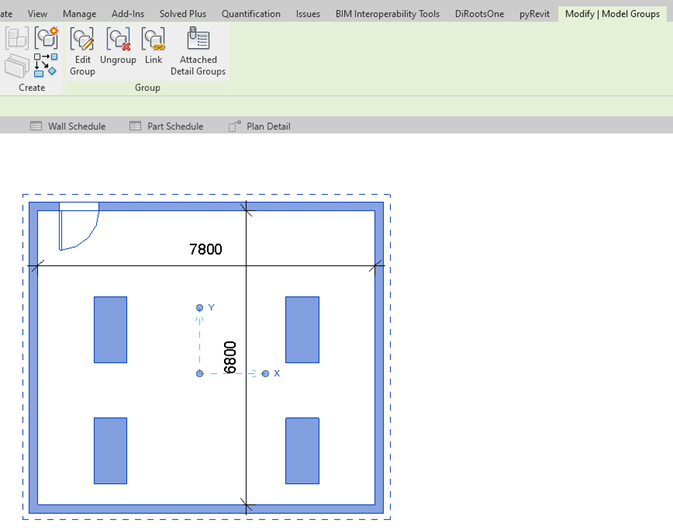
Whereas Group is useful when we have repetitive elements or layout.

2. Elements

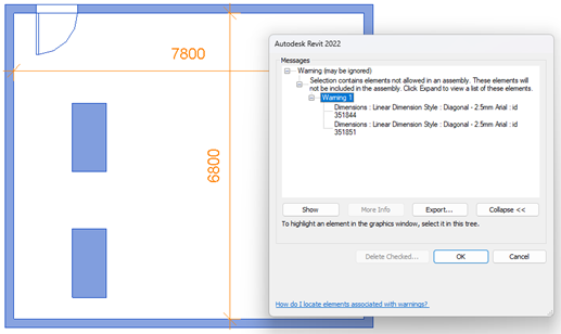
Assembly cannot be created containing rooms, annotation, and detail items.

Assembly – Element

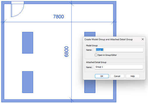
Whereas Group can be created containing rooms, annotation & detail items. (Model Group, Detail Group)

Group – Element

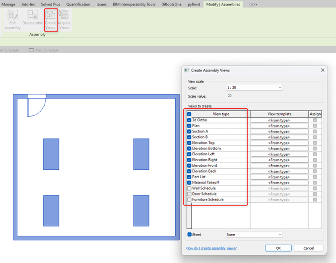
3. Separate Set of Views

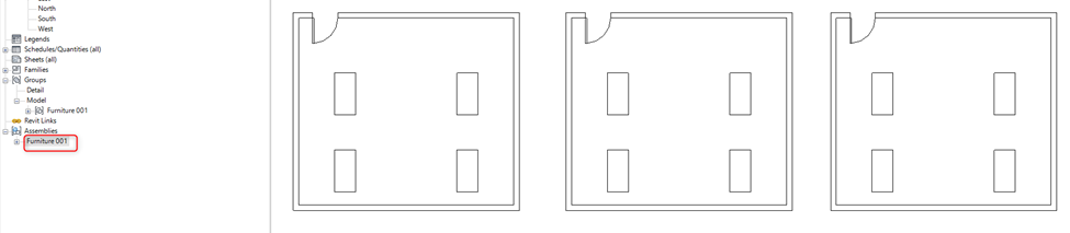
Assembly provides a function to create a different set of views (Floor Plans / Ceiling Plans/ Elevation/ Section/ 3D Views/ Schedule) just containing that assembly.

Assembly – Separate Views

Whereas Group does not have a such function of creating a separate set of views just for the group.

Group – Separate Views

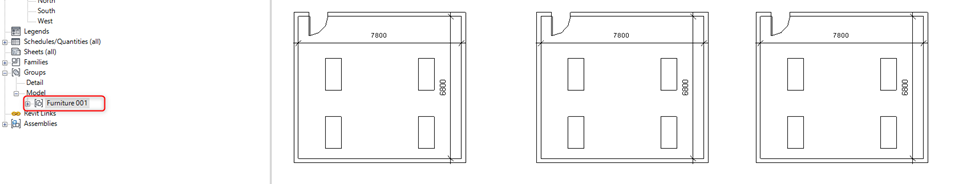
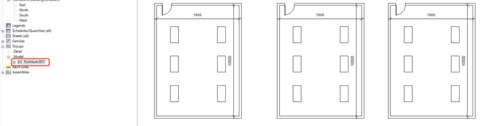
4. Editing Capabilities

Assembly when edited creates a separate assembly it doesn’t make changes in similar assemblies in the project. This means when the assembly is created design must be completed.

Assembly – Before Editing
Assembly – After Editing

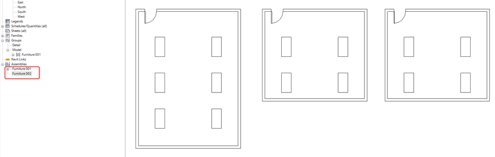
Whereas when edits are made inside a group do not create a separate group instead it updates all the similar groups in the project.

Group – Before Editing
Group – After Editing

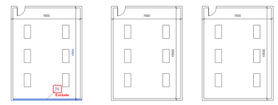
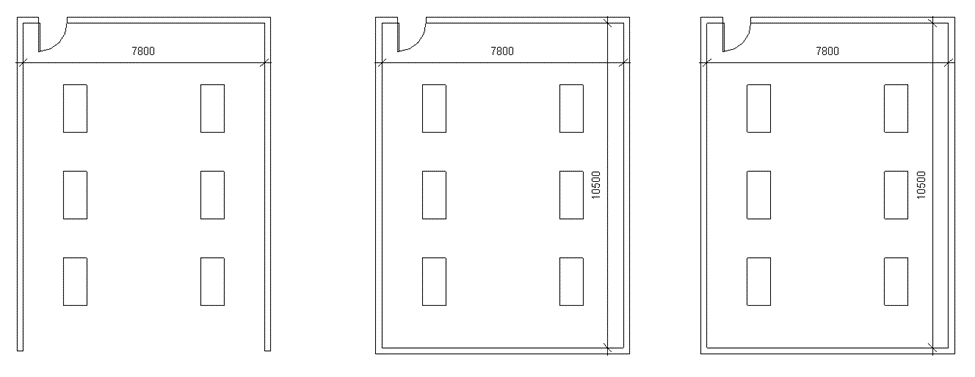
5. Exclusion of Elements

Assembly does not have a separate function of exclusion, unlike Groups.

Whereas in a Group when a single element of a group is excluded it doesn’t make changes in similar groups. It also has the option of restoring all excluded elements in a group. It provides more flexibility in terms of making changes in a group

Group – Before Excluding Element
Group – After Excluding Element (Wall)

6. Deletion

When a particular assembly is deleted in a view it completely gets deleted from the project.

Whereas when a Group is deleted in a view it remains in the project and can be used later to place back in the project.

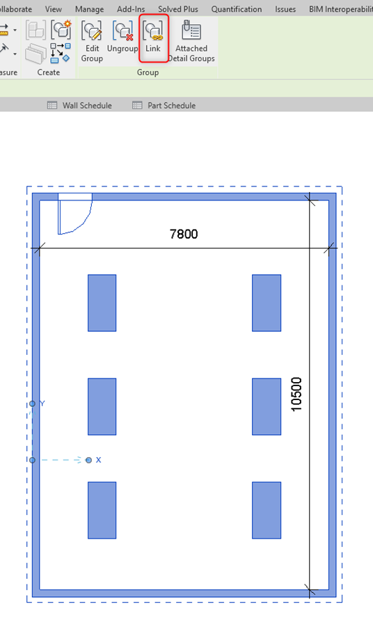
7. Separate Revit Link

Assembly cannot be created as a separate link.

Whereas Group can be converted into a separate Revit Project and linked into the current file as a Revit Link.

Group – Separate Revit Link

Summary

Can include multiple ElementsSeparate ViewsFlexibility to EditCan include RoomsCan include Annotation/Detail ItemCan include Design OptionExclude certain element
GROUPYesNoYesYesYesYesYes
ASSEMBLYYesYesNoNoNoNoNo
Group vs Assembly

Worksets


To understand worksets it’s essential to understand their role.

A Workset is used in a Revit Workshared Model.

What is a Workshared Model?

The workshared model is a Model where many team members can collaboratively work on the same model at the same time.

Purpose of Workset

As multiple users will be working on the same model it is essential to divide the project elements within parts so that the entire model can be editable by all users,

When a particular workset is made editable the ownership of that workset (containing all elements within it) will be given to that user while working.

No two users can edit elements of the same workset at the same time.

Workset Segregation

To achieve better collaboration, elements are segregated in the worksets depending on what is the role of different members in modeling.

Workset can be made in terms of functional areas of the project if team member work is divided as per functional areas or Worksets can be made in terms of the category of elements if team member work is divided as per the category of elements (Doors, Windows, Walls, Ducts, Piping, etc.)

Benefits of Worksets

Collaborative Working

It provides convenience for editing the project when multiple users are working together.

Visibility

It can also be used to control visibility. The workset can be turned off in a view when not desired. Also, filters can be created using workset.

Faster Opening of Model

If a model must be opened just for viewing/checking the purpose some worksets can be put off to open the model faster.


Essential Points while Segregating Workset

1. All Levels & Grids must be in the same workset in “Shared Levels & Grids.”

2. Every Revit Link must be in a separate workset with a proper naming as “+Link_LinkFileName”

3. And each workset must have a prefix of Discipline Code – “A_” for Architecture; “M_” for Mechanical and so on.


Workset Creation

1. Click Collaborate tab > Worksets (Manage Collaboration panel)

2. In the Worksets dialog, click New.

3. In the New Workset dialog, enter a name for the new workset.

4. To display the workset in all project views, select Visible in all views.

Clear this option if you want the workset to display only in views where you specifically turn on its visibility.

You can change the visibility of worksets later in the Visibility/Graphics dialog.

5. Click OK > Close the Worksets dialog.

When a new workset is created it prompts you to make the new workset active. Click Yes or No depending on use.

Manage Revit Link Worksets

1.Click Manage Tab > Manage Link (Mange Project panel)

2. Select Revit Link for which you want to edit a workset visibility

3. Click Manage Worksets

4. Select Worksets you want to close/open from Revit Link to make it visible/hidden in your current project.

5. Click Reload > Click Ok


Understanding Revit Parameters


What is a Parameter?

Parameters are properties of an element that shows and controls the element’s information.

Types of Parameter

  • INSTANCE PARAMETER
  • TYPE PARAMETER
  • PROJECT PARAMETER
  • SHARED PARAMETER
  • GLOBAL PARAMETER

Instance Parameter

To understand these parameters first understand the term “Instance” which means a single occurrence of something.

Therefore, an instance parameter means a parameter of an element that can be modified for each element/instance.

The parameters which appear on the properties tab (outside) of every element are instance parameters.

Properties Dialog Box (Example: Wall Properties)

Type Parameter

The term “Type” means a category of people or things having common characteristics.

Therefore, type parameter means a parameter of the type of element which can be modified across all types of elements. It is not instance based.

The parameters which appear after clicking “Edit Type” on the properties tab of the element are type parameters

Properties Dialog Box > Edit Type (Example: Wall Properties)

Project Parameter

The word Project stands for “Entire Model” in Revit Terminology.

Therefore, these parameters are for the “Entire Project” and are not specific to a single element or family type. Project Parameters are for entire categories or categories of elements.

Project Parameters can be Instance Parameters or Type parameters. So, depending on its application it can be defined which one is appropriate.

Project Parameters can only be scheduled it cannot be used to create a tag.

If Shared Project Parameter is created, then those parameters can be scheduled and can be used to create a tag as well.

Manage Tab > Project Parameters

Family Parameter

The word Family stands for .rfa files in Revit Environment.

Hence, these parameters are for a particular family which is created when creating a parametric family enabling it to flex.

Family Parameters can be Instance Parameters or Type parameters. So, depending on its application it can be defined which one is appropriate.

These parameters cannot be scheduled, nor can be used to create a tag unless those are created as Family Shared Parameter.

Shared Parameter

Shared Parameters are parameters that can be “Shared” across multiple projects/families.

Shared Project Parameters or Shared Family Parameters enable it to be scheduled as well to create a tag.

It ensures uniformity of parameter name, parameter discipline & type of parameter (text, number, length, integer, etc.) when used across multiple projects/families.

Manage Tab > Shared Parameters

Global Parameter

Global Parameters are parameters that are not defined to any element/type or category.

It is used to control geometry by building relationships between different elements. Also, it can be used to create complex parametric relationships between elements by using formulas in global parameters.

Manage Tab > Global Parameters

Hence, it is very essential to understand which parameter must be created for what requirement.

Example:

You have a box family. And the box is placed 10 times in a project. For 5 instances length is 2000, and for the other 5 instances it’s 1500 mm; the width is 5000 mm for all 10 instances whereas height is varying for each instance from 200, 300, 400, 500, 600, 700, 800, 900, 900, and 1000 mm respectively;

Height is varying for each instance then create that as an instance family parameter.

Width is constant throughout 10 instances, create width as a type family parameter.

Since element length has only two varying values, create it as a type family parameter. Also, create 2 types in the family with different length parameter values.

If the above parameters are required to be scheduled/tagged then create those as shared family parameters.


Essential Guides & Standards


BIM Little Book

One can start with this to understand various acronym associated with BIM and which standards specifies what.

PAS Standards

PAS 1192-2

Specification for information management for the capital/delivery phase of construction projects.

PAS 1192-3

Specification for information management for the operational phase of assets

PAS 1192-4

Briefing for design and construction Code of practice for facilities management

PAS 1192-5

Specification for security-minded building information modelling, digital built environments and smart asset management

PAS 1192-6

Specification for collaborative sharing and use of structured hazard and risk information for Health and Safety

Other Key Standards

BS 8536 Part 1 & 2

Briefing for design and construction. Code of practice for facilities management (Buildings infrastructure).

Briefing for design and construction. Code of practice for asset management (Linear and geographical infrastructure).

BS 8541-1:2012

Library objects for architecture, engineering and construction. Identification and classification. Code of practice

BIM Protocol

It’s a standardized supplementary legal agreement that can be incorporated into professional service appointments and construction contracts by a simple amendment.

Information Management according to BS EN ISO 19650

Part 1- Concepts

Part 2- Process for Project Delivery

Information Protocol to support BS EN ISO 19650-2 the deliver phase of assets

RIBA

RIBA Plan of Work

The RIBA Plan of Work organises the process of briefing, designing, constructing and operating building projects into eight stages and explains the stage outcomes, core tasks and information exchanges required at each stage.

RIBA Sustainable Outcome Guide

The Sustainable Outcomes Guide aligns with the UN Sustainable Development Goals, and outlines eight clear, measurable goals that practices can aim for on projects of all scales, underpinned by specific design principles to achieve them.

Planning Guides for BIM Implementation

BIM Execution Planning Guide

This Guide provides a structured procedure for creating and implementing a BIM Project Execution Plan. There are template links of BIM Project Execution Plan, Goal & Use Worksheet, Process Maps & Information Exchange templates in Appendix J.

BIM Planning Guide for Facility Owners

Uses of BIM

BIM Building Execution Plan (BEP) Template

Pre-Contract Stage:

Pre-Contract BIM Execution plan should include:

  • A project implementation plan (PIP) setting out the capability, competence and experience of potential suppliers bidding for a project, along with quality documentation.
  • Goals for collaboration and information modelling.
  • Project milestones in line with the project programme.
  • Deliverable strategy.

Post-Contract Stage

Post-Contract BIM Execution Plan should include:

  • Management
  • Planning & documentation
  • Standard method & procedure
  • IT Solutions

Assessment Templates

BIM Uniclass 2015

  • Uniclass is a consistent classification structure for all disciplines in the construction industry, an essential way of identifying and managing the vast amount of information that’s involved in a project.
  • It’s a requirement for BIM projects, as set by the BS EN ISO 19650 series of standards.
  • It is divided into a set of tables which can be used to categorize information for costing, briefing, CAD layering, annotations, etc. as well as when preparing specifications or other production documents under one unified scheme.
  • Divided into 12 suits as follows:
  1. Ac- Activities
  2. Co- Complexes
  3. EF- Elements/Functions
  4. En- Entities
  5. FI- Form of Information
  6. PM- Project Management
  7. Pr- Products
  8. Ro- Roles
  9. SL- Spaces/ Location
  10. Ss- System
  11. TE- Tools & Equipment
  12. Zz- CAD

Uniclass 2015 Templates

Lean Essentials


What is Lean??

  1. Operations: It is an operational strategy to increase productivity by flow of efficiency
  2. Project Delivery: It shreds away unnecessary effort, time & cost in project development to provide what owner’s values.
  3. Design: Creative process to prevent error & invent value

Lean Progression©

Lean Waste

It is said 70% of activities performed are non-value added or waste.

Japanese word “Muda-Mura-Muri”

Muda means Waste

TransportationUnnecessary process movement
InventoryQuantities beyond immediate need
MotionMovement that adds no value
WaitingWork in progress, stalled
Over processingFinishing beyond need
Over ProductionCreating before need
DefectsRework
TalentUnderutilized people
DisrespectConsuming resources

Mura means “Overburdening”

Push PlanPressing beyond system limit

Muri means “Unevenness”

VariationUnreliable demand

Benefits


1. Visualization

BIM adoption helps in visualizing entire project digitally before construction. There is no misunderstanding between imagination by the client and what architect or any designer wants to portray.

2. Collaboration

It helps in integrating model by all disciplines into one single model. It helps in visualizing project as a whole.

3. Change Management

If change is done by one discipline is sent as notification/mail to all other assigned to make respective changes as per new design. It is easier to understand and visualize. By this changes can be done virtually without conducting a physical meeting for each change or by sending mails separately to each discipline.

4. Management

It is easier to understand and visualize entire construction flow of the project until completion. It is easy to monitor and control in 3D model what was planned then what was completed.

Graphical representation also helps in understanding various stakeholders the progress of the project.

5. Quantification & Costing

By BIM adoption accurate quantities can be estimated before actual execution of the project which reduces delay in project due to cost overruns. It helps in efficient cost planning and including lean, value engineering at initial stage itself.

6. Clash Detection

It helps in identifying any clashes between each discipline design rather than realizing it during construction which leads to demolition and again constructing those parts which leads to time, money, materials wastage; increased project schedule & cost.

7. Facility Management

It helps in keeping track when any part of project have to serviced notifies about it beforehand. It also helps in managing data whichever is required during operation stage of building.

“It is a myth BIM Implementation will take away jobs of certain disciplines”

BIM helps in efficient & effective planning, transparency, monitoring, controlling, managing the entire project from initiation till entire life-cycle of project. It is helpful to each stakeholder involved client, investors, insurers, architects, engineers, various consultants, masons, government body, end user, etc.

It helps in:

  • Saving time (On time completion/ no delays)
  • Efficient Cost Planning (no cost overruns)
  • Data Management
  • Construction Management
  • Efficient Collaboration
  • Better Visualization for all stakeholders
  • Effective Change Management
  • Analyzing various analytical aspects
  • Helps in adopting sustainability features & analyzing
  • Helps in facility management

BIM TOOLS


BIM Tools are softwares which help implementing BIM in any construction project.

In following tools are segregated in different categories of workflow though some tools can be used in many categories.

(By clicking on tools name it will take to tool website where you can download free trial or purchase tool, videos give brief overview of tool)

Category 1: BIM Execution Planning Tools

Plannerly

Category 2.1: Modeling Tools

Rhino

Bentley MicroStation

Mostly used for infrastructure projects

Category 2.2: Structural Modeling

Category 3: BIM Content/BIM Objects

For implementing BIM for the project it requires BIM families or BIM objects which have all specifications along.

MagiCAD

Mainly for MEP solutions

Category 4: Algorithmic Aided Design (Modeling)

Category 5: Performance/Analysis Tools

Autodesk Green Building Studio

Used with Autodesk Revit

Trimble- Sefaira

Used with SketchUP

Ladybug

Used with Dynamo & Grasshopper

BIM Management Process


01. Employee Information Requirements (EIR)

  1. Firstly, it should be developed by clients.
  2. But if client is not much aware then contractor can prepare by asking questions to the client.
    1. Example:
      • Why you want to design & construct?
      • What information you need to hand over to operate building
    1. This will help in:
      • Competitive Edge
      • Look more professional
      • Customer Satisfaction
      • Successful Project
      • Better Reputation

EIR should cover:

  1. Technical
    • Level of definitions (Maturity Levels)
      1. Level of information (non-graphical)
      2. Level of Detail (Graphical-3D Model)
    • File Types
    • Softwares/Tools to be used
    • File Format
  2. Management
    • Key personnel qualifications, roles, responsibilities
    • Specification & Standards
    • Security Standards
    • Key Decision Points
  3. Commercial
    • Strategic Purpose (Non-Profit/ Profit)
    • Budget
    • Cash Flow
    • Competencies & competitive advantage of project

BIM Essentials


What is BIM?

Building Information Modeling (BIM) is an intelligent 3D model-based process that gives architecture, engineering, and construction (AEC) professionals the insight and tools to more efficiently plan, design, construct, and manage buildings and infrastructure. (source: Autodesk)

  • Higher Quality
  • More Efficiency
  • Room for Improvement & Assessment
  • Digitally stored information for asset management
  • Improvement in facility management & maintenance
  • 20%-25% of costs can be saved

Dimensions

3D– An object defined with length, width & height

4D– Integrating Time factor

5D– Integrating Cost factor

6D– Integrating Facilities Management

Maturity Levels